LED Lighting SMT Lines: When Do You Need a Dedicated Lens Mounter?
When lens placement deserves its own machine on an LED lighting or backlight line, where the lens step sits in the process, and what to check before you buy a lens mounter.
5 min read
Many LED lighting and display backlight products put a secondary optical lens over each LED. The lens shapes the light: it spreads it evenly across a backlight panel, throws it along a wall, or focuses it into a beam. On a board carrying dozens or hundreds of LEDs, that means dozens or hundreds of lenses to place accurately.
Lenses can be placed by hand, by a general-purpose mounter, or by a machine built for the task. This guide explains when a dedicated lens mounter makes sense and how it changes the rest of the line. Choosing between LED and standard mounters for the LEDs themselves is covered in our separate guide to LED and standard placement machines.
Why lenses are a separate placement problem
A lens is not an electronic component. It is usually a molded plastic part, often taller than the LED below it, sometimes with legs or locating features, and frequently supplied in bulk rather than on tape. It must sit centered over its LED, because a small offset changes how the light spreads.
These differences affect almost every part of the machine: how lenses are fed, which nozzles hold them, how the camera recognizes clear or irregular shapes, and how tall a part the head can handle. A machine optimized for small LED packages on tape is not automatically good at lenses.
Where the lens step sits in the process
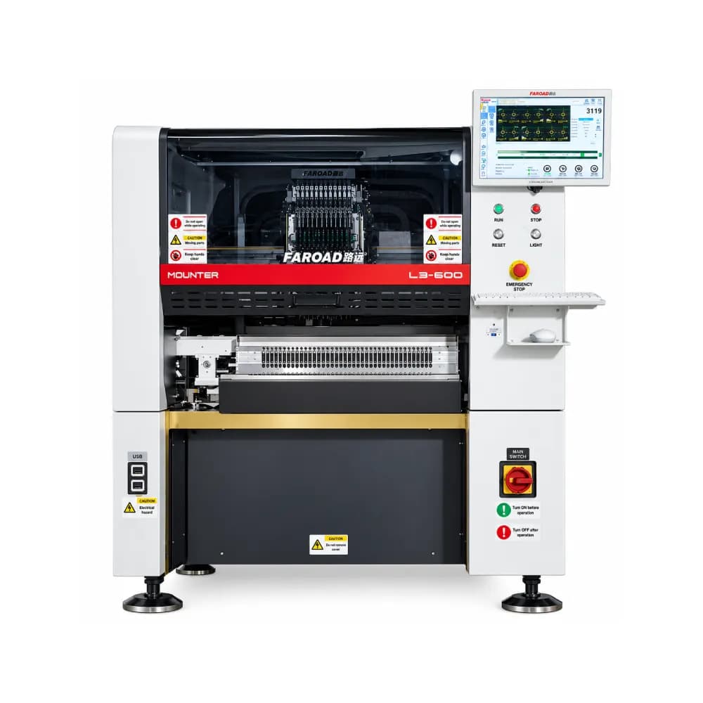
The LEDs and the lenses are usually placed at different stages. In many backlight and lighting processes, the LEDs are soldered first, and the lenses are attached afterwards, typically with adhesive that is then cured. Lens materials and adhesives have their own temperature limits, so the lens step often comes after reflow rather than before it.
Confirm the exact sequence with your lens and adhesive suppliers, because it decides your line layout. If lenses go on after reflow, you need a second placement stage downstream of the oven, plus adhesive dispensing and curing. If your lens design is soldered or clipped, the sequence may differ. Either way, write the sequence down before asking for equipment quotations.
Signs a dedicated lens mounter will pay its way
A machine built for lenses is usually justified when several of these apply:
- High lens count. Each board carries many lenses, and lens placement is a large share of total placement time.
- Varied lens shapes. Your products use bipedal, triangular, wall-washer or other special-shaped lenses.
- Bulk-supplied lenses. Lenses arrive loose rather than on tape, so vibration or bulk feeding is needed.
- Long boards. Backlight strips and linear fixtures exceed the board length a general mounter accepts.
- Hand placement is limiting. Manual placement cannot keep up, or offset is causing optical rejects.
When you can manage without one
A dedicated machine is harder to justify if lens counts are low, if your lenses are supplied on tape and fall within a general multifunctional mounter's component range, or if lenses are mechanical parts fitted later in final assembly. In those cases, a capable LED or multifunctional mounter, or a fixture-based manual process, may be enough.
What the CPM-L3T specification tells you to check
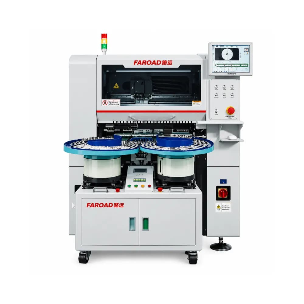
FAROAD's CPM-L3T lens mounter is a useful reference for what to look for. Its page lists:
- Two head types. An 8-nozzle high-precision head (0821R) with independently controlled rotation axes, for TV backlight lenses up to 17 × 17 mm and 13 mm thick, and an 8-nozzle high-speed head (0821BL) for bipedal, triangular, wall-washer and special-shaped lenses.
- Speed and accuracy. A best placement speed of 28,000 CPH (IPC-9850) and accuracy of ±0.08 mm.
- Feeding. A vibration feeding device with customizable vibrator, nozzle and component identification, and 20 feeder stations in 8 mm terms.
- Vision. A module camera with 8 independent cameras that identifies 8 parts at once without stopping.
- Board size. 50 × 50 mm up to 600 × 400 mm in single-section mounting, and up to 1,200 × 400 mm in two-section mounting, with board thickness from 0.4 to 9.5 mm.
Use this as a checklist when comparing any lens mounter: head types for your lens shapes, feeding method for your lens supply, vision for clear parts, and board length for your longest product. Then confirm with a trial using your lenses.
Lay out the line around two placement stages
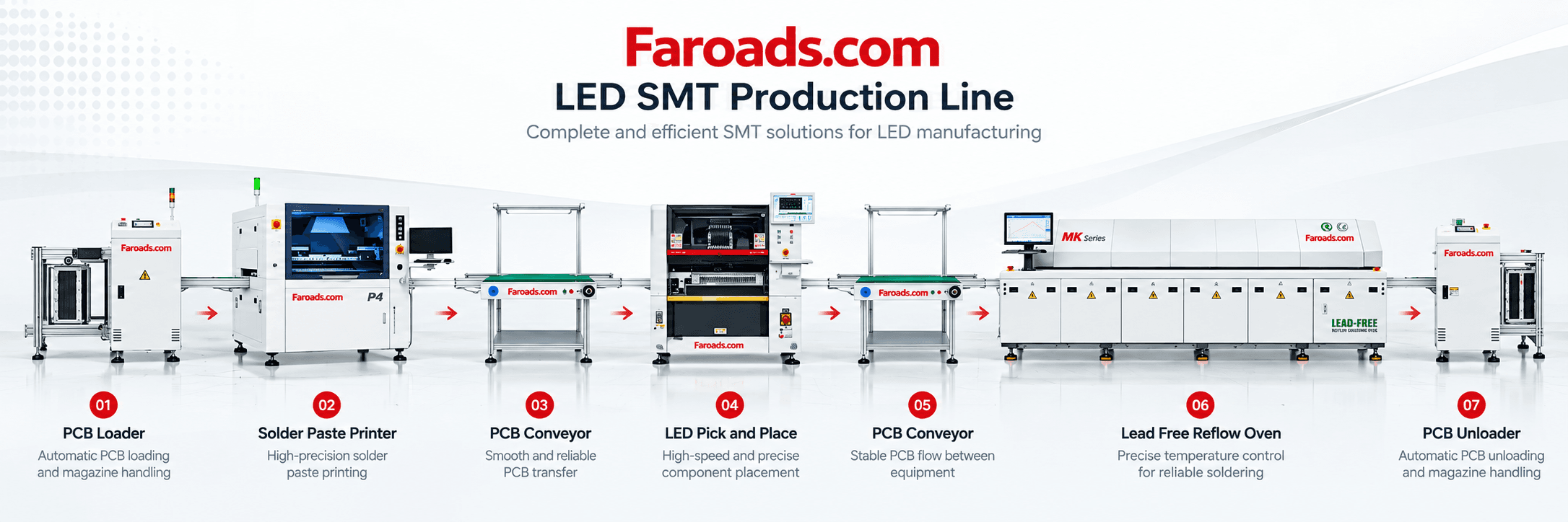
If lenses go on after reflow, the line has two placement stages separated by the oven. Plan the board flow so the lens cell can keep pace with the LED stage. Decide whether it runs inline, directly after reflow and inspection, or as a separate cell fed by magazines.
An inline layout reduces handling but links the two stages, so a stop in one affects the other. A separate cell adds handling but allows the lens stage to run on its own schedule. The right answer depends on volumes and how often products change. Long boards also need conveyors, buffers and handling that match their length, as explained in our guide to long-board LED lines.
Inspect before the lenses hide the joints
Once a lens is attached, the LED's solder joints are much harder to see. Inspect LED placement and soldering after reflow and before the lens stage, so defects can be repaired while they are still accessible.
After lens placement, check lens position and presence. Optical tests of the finished board can then confirm that the light output meets specification.
Frequently asked questions
Can a standard pick-and-place machine place lenses? Sometimes, if lenses are on tape and within its component range. Bulk feeding, special shapes and long boards usually favor a dedicated machine.
Are lenses placed before or after reflow? In many processes, after reflow with adhesive. Confirm with your lens and adhesive suppliers.
What accuracy do lenses need? It depends on the optical design. Ask your lens designer for the allowable offset and compare it with the machine's published accuracy.
Do we need a separate line for lenses? Not always. A lens cell can sit inline after reflow or run separately; volume and changeover frequency decide.
Request a lens-line configuration
Send FAROAD your board drawings, lens types and target output, and we will recommend a lens placement setup and line layout. Request a quote with samples or drawings of your lenses.