Pick-and-Place Accuracy: How to Read the Spec and What Your Boards Need
A placement accuracy figure only means something with its statistics and test conditions. Here is how to read the spec, turn your smallest parts into a requirement, and verify it before you buy.
4 min read
Every pick-and-place quotation includes an accuracy figure, usually a few hundredths of a millimeter. Buyers tend to compare those numbers directly and pick the smallest. That can lead to paying for precision your boards do not need, or to trusting a figure that was measured under conditions your production will never see.
This guide explains how to read an accuracy specification, how to turn your own components into a requirement, and how to check the machine before you commit. For the broader machine decision, see our pick-and-place selection guide.
What the accuracy number actually says
A placement accuracy figure describes how far placed components land from their programmed positions. On its own, a figure such as ±35 µm is incomplete. A meaningful specification adds two qualifiers.
A statistical basis. Placements vary randomly around an average. The specification should say how much of that spread the figure covers, expressed in sigma (σ) or as a capability index such as Cpk. A figure at 3σ means about 99.7% of placements should fall inside it if the process is centered; a figure at 4σ covers a larger share and is a stricter claim.
Test conditions. Manufacturers measure accuracy with specific test components, heads and speeds, on a calibrated machine in a controlled room. The industry method for this is IPC-9850; a Circuits Assembly explainer on IPC-9850 describes how it defines capability.
Also separate three terms that are sometimes mixed together. Accuracy is how close placements come to the target. Repeatability is how tightly they cluster, wherever that is. Resolution is the smallest step the motion system can make. Only the first two tell you about placement quality.
Reading Cpk on a datasheet
Cpk compares the allowed tolerance with the actual spread and offset of the process. A Cpk of 1.0 means the tolerance limit sits about three standard deviations from the average. A Cpk of 1.33 means about four standard deviations, and fewer placements fall outside.
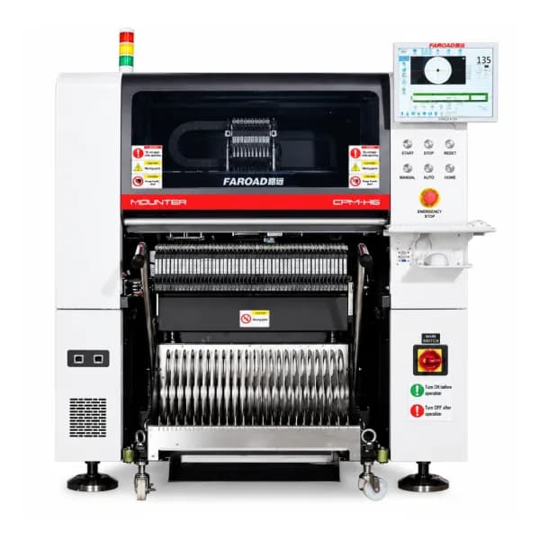
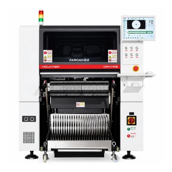
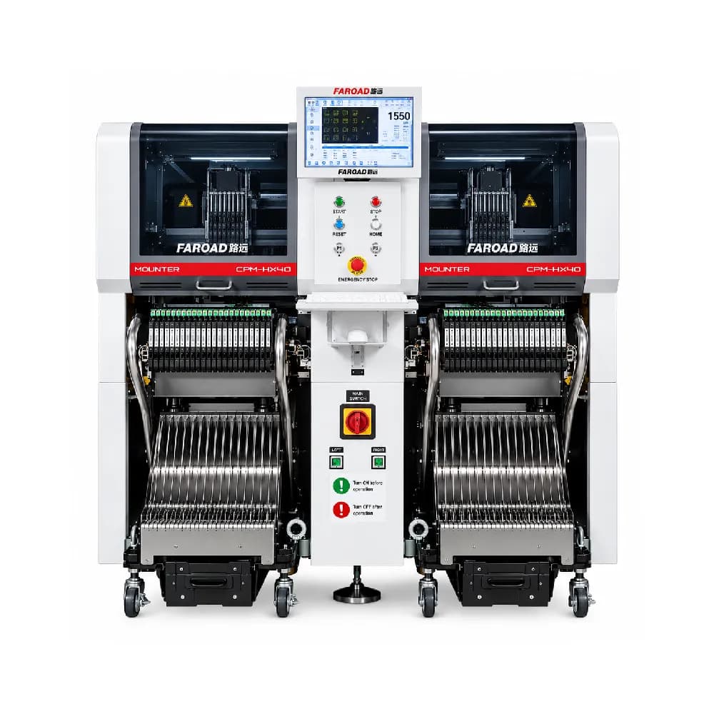
FAROAD's mounters show this format. The CPM-F5, CPM-F6, CPM-H6 and CPM-S5 list ±0.035 mm with the high-speed head and ±0.03 mm with the multifunctional head, both at Cpk ≥ 1.0. The CPM-HX40 lists ±0.025 mm at Cpk ≥ 1.0, with a component range down to imperial 01005. Because each figure is tied to a head type, check which head would place your most demanding parts.
Work out what your boards need
The right question is not “which machine is most accurate?” but “how much placement error can my smallest and finest-pitch parts tolerate?”
Start with your process engineer or board designer. For each critical part type, agree a maximum offset beyond which the joint is at risk. That depends on pad design, paste deposit and how much the part self-aligns during reflow. Small chips tend to pull themselves toward the pads as solder melts; large leaded ICs move less.
Then compare the machine against that limit. An illustrative example, not measured data: if a specification of ±35 µm at Cpk 1.0 represents three standard deviations, the spread is about 11.7 µm per standard deviation.
- For a chip whose allowed offset is 60 µm, the resulting Cpk is about 1.7, a comfortable margin.
- For a fine-pitch lead whose allowed offset is 40 µm, the Cpk drops to about 1.1, which leaves little room.
- A ±30 µm head raises that second case to about 1.33; a ±25 µm machine to about 1.6.
This simple check shows where a more accurate head or machine earns its cost and where it does not.
Speed and accuracy are linked
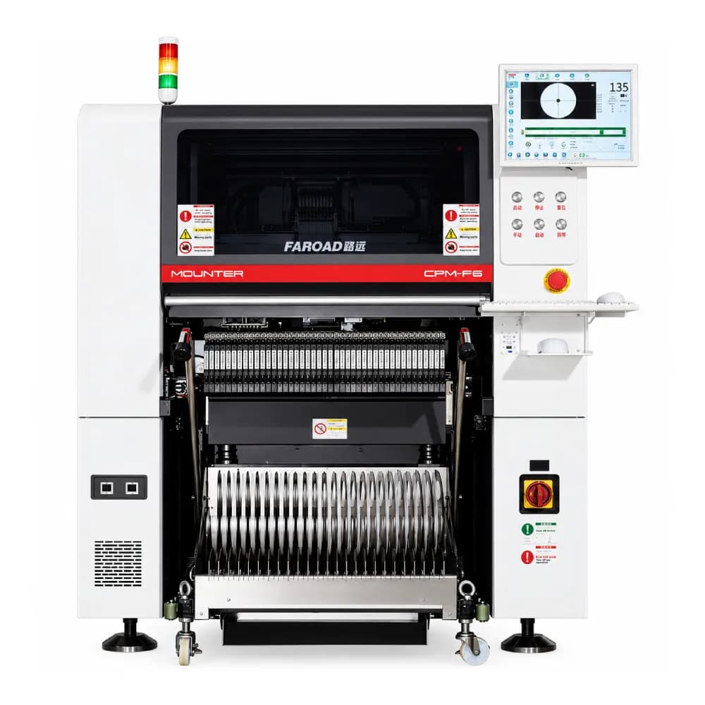
High-speed heads with flying cameras recognize parts while moving, which saves time. Multifunctional heads with fixed cameras usually handle larger and finer parts more precisely. FAROAD's published figures reflect this: on the CPM-F6, the high-speed head is rated at 42,000 CPH and ±0.035 mm, while the multifunctional head is rated at 18,000 CPH and ±0.03 mm.
If only a few parts on each board need the tighter figure, a line that places them on a precision head while chips go to a high-speed head can deliver both throughput and accuracy. Balance the program so neither head becomes the bottleneck.
Accuracy over the life of the machine
A new machine meets its specification after calibration. Keeping it there depends on nozzle condition, feeder pickup, board support and the factory environment. Ask what the machine does to hold accuracy. Several FAROAD models, including the F5, F6 and HX40, list automatic correction with thermal compensation. Also ask how often calibration should be checked and what tools it needs.
Verify before you buy
A datasheet is a starting point. Before you sign:
- Ask under which conditions the accuracy figure was measured, which head and which test components were used.
- Run a placement trial with your own critical parts, ideally on a glass or test board that can be measured, at the speed you plan to run.
- Calculate Cpk from the measured offsets against your own tolerance limits, not the brochure's.
- Write the agreed accuracy test into the acceptance criteria for installation.
The FAROAD pick-and-place range lists accuracy, head type and component range for each model, which makes it easier to shortlist before trial.
Frequently asked questions
Is a smaller accuracy number always better? Only if your parts need it. Paying for a tighter specification than your boards require adds cost without improving yield.
What Cpk should I ask for? Many manufacturers aim for 1.33 or higher on critical parts in production. Agree the target with your quality team.
Does placement accuracy matter if components self-align? Yes. Self-alignment helps small chips but has limits and does little for larger leaded parts. Accuracy still sets your starting margin.
Can accuracy drop at higher speed? It can. Ask whether the figure applies at the speed you intend to run, and test at that speed.
Request an accuracy review
Send FAROAD your component list, the smallest and finest-pitch parts and your target output. We will recommend a head and machine configuration and propose an accuracy test. Request a quote to begin.