Pick-and-Place Vision Systems: Flying, Fixed and Line-Scan Cameras for Buyers
How the cameras on a pick-and-place machine decide which parts it can place and how fast, how to map your BOM to flying and fixed camera ranges, and what to test before you buy.
5 min read
Brochures sell a pick-and-place machine on speed and accuracy. Both numbers depend on the cameras. The vision system decides which components the machine can recognize, how long recognition takes, and how well it corrects for a board that is not exactly where the program expects. This guide explains the camera types in plain terms and shows how to turn them into purchase questions. For what an accuracy figure means on paper, see our pick-and-place accuracy guide.
Three jobs the vision system does
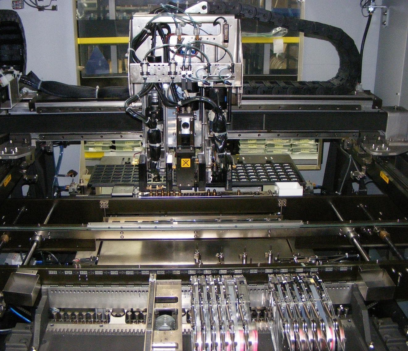
Inside a surface-mount placement machine: gantry, placement head with cameras, tray parts and tape feeders. Photo: Peripitus. Source on Wikimedia Commons, CC BY-SA 3.0. Recompressed as JPEG for publication; not cropped or resized. This file is shared under the same license.
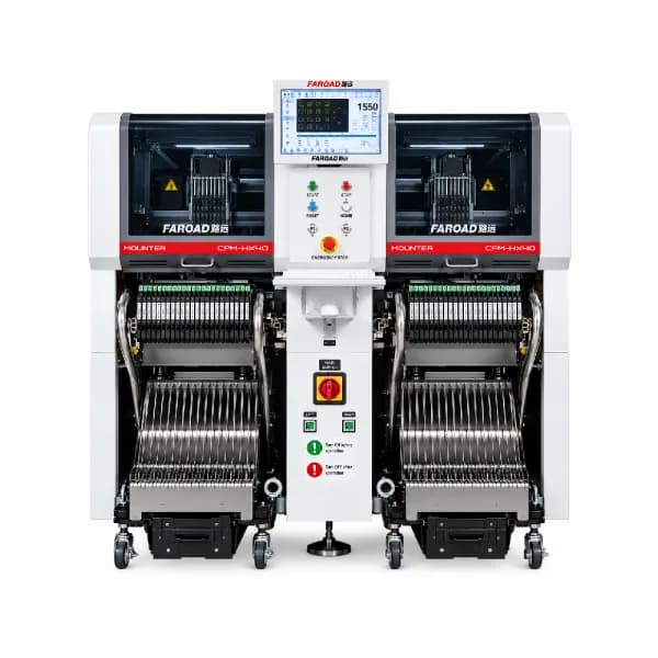
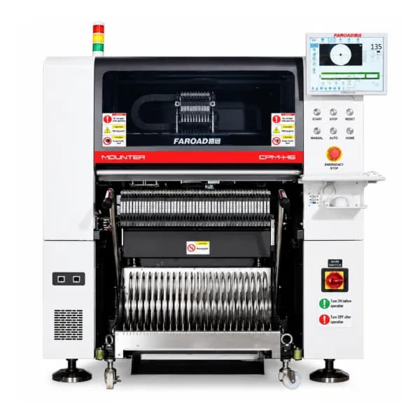
Finding the board. A downward-looking mark camera reads fiducials so the machine knows the real position and rotation of the panel. On the FAROAD CPM-F5, F6, H6 and S5, the mark camera is listed as a 500W area-array type with a 20 × 20 mm field of view. The CPM-HX40 lists a 10 × 10 mm field. A smaller field means fiducials need to sit cleanly inside a tighter window.
Seeing the part on the nozzle. After pickup, an upward view measures where the component actually sits on the nozzle, including its angle, so the head can correct before placing. This is the step that separates flying and fixed cameras.
Supporting the program. Recognition data for each part number lives in a component library. How easily that library is built and shared matters as much as camera hardware on a high-mix floor.
Flying cameras: recognition while the head moves
A flying camera travels with the head and images parts during the move from feeder to board. No detour is needed, which is why high-speed heads use it. The trade-off is size. On the F5, F6, H6 and S5 high-speed heads, flying cameras handle parts from imperial 0201 to a 12 × 12 mm body no taller than 6.5 mm. Chips, small transistors and small ICs fall inside that window; larger packages do not.
Fixed cameras: larger and finer parts
A fixed camera sits on the machine frame. The head carries the part over it, stops or slows, and the camera takes a sharper, larger image. That is slower, but it handles bigger bodies and finer leads.
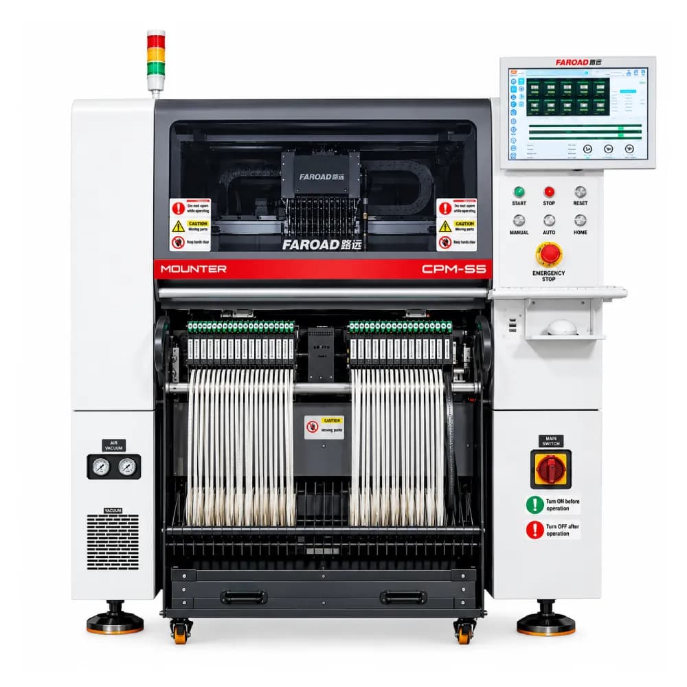
The FAROAD listings show the difference clearly. With the multifunction head and its fixed camera, the F6 and H6 reach 55 mm square parts and the F5 and S5 reach 40 mm square, each up to 25 mm tall. The price is speed: on the F5 and F6, the multifunction head is rated at 18,000 CPH against 42,000 for the high-speed head, while on the H6 and S5 it is 38,000 CPH against 90,000 and 84,000. The HX40 uses a fixed camera only, over a deliberately narrow range: imperial 01005 up to 6 × 6 × 3 mm.
Line-scan and module cameras
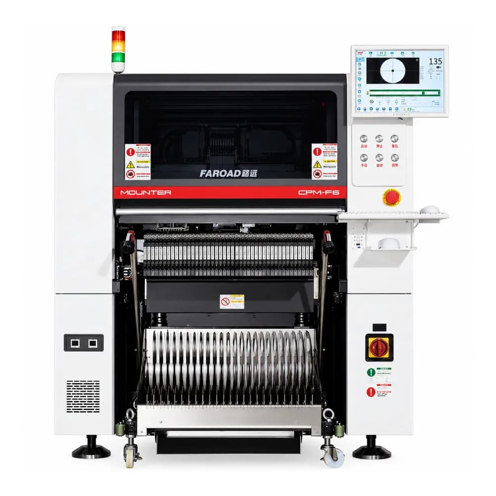
Some machines replace or supplement single snapshots with cameras that capture several parts in one pass. The CPM-F5 and F6 list a linear scanning camera system. FAROAD's LED machines describe area or module cameras that recognize multiple component types together, and the CPM-L3T lens mounter lists a module camera with eight independent cameras that identifies eight materials without stopping during Y-axis travel.
The buyer point is not which method sounds newer. It is whether the method recognizes your exact parts at the speed the quote promises.
Map your bill of materials to the camera envelope
Before comparing machines, sort every part number into three groups:
- Flying-camera parts. Inside the listed flying range; these drive high-speed head output.
- Fixed-camera parts. Larger, taller or finer-pitch packages that need the multifunction head.
- Outside the listing. Anything above the largest fixed-camera range, unusual shapes or connectors that need a gripper. These need a specific answer from the supplier, or a different process.
Then count placements in each group per board. A machine with an impressive high-speed figure can spend most of its time on the fixed camera if your design is IC-heavy. The high-speed versus modular placement guide explains how that mix changes the right machine class.
Also ask how parts are taught. For the CPM-F6, FAROAD describes importing placement coordinates from TXT or spreadsheet files, editing odd parts in the library, and keeping the part database in step across machines over the local network. The S5 lists the VConnector offline programming software. Those features shorten new-product setup only if your engineers can use them on your file formats.
What to test in a vision trial
A vision trial should use your real reels, trays and boards, not a demonstration panel. Record:
- Recognition rejects per part number, not just a machine-wide average. One troublesome package can stop a line.
- Recognition time effect on cycle, especially for parts that move to the fixed camera.
- Fiducial reads on your solder mask colour, finish and any fiducials near the panel edge.
- Teach time for a new part that is not in the library.
- Drift over a shift. Thermal compensation appears on the F5, F6 and HX40 pages; ask what triggers a correction and whether it is logged.
Placement problems that look like vision faults are often feeder, nozzle or support issues. Our placement defects guide helps separate the causes.
Frequently asked questions
Is a flying camera less accurate than a fixed one? Not necessarily for the parts it is designed for. Its limit is the size window. Larger or finer-pitch parts are listed on fixed cameras because they need a larger, steadier image. Why does the multifunction head have a lower CPH rating? It places larger parts, uses fewer nozzles and routes parts over a fixed camera. On the FAROAD listings, its rating is less than half the high-speed head's. Can the HX40 place a 10 × 10 mm QFN? Its listed fixed-camera range stops at 6 × 6 × 3 mm, so that package is outside the published range. Pair it with a machine whose multifunction range covers the part. How many fiducials should the panel carry? At least two global fiducials, placed well apart, plus local fiducials near fine-pitch parts are common practice. Confirm the mark camera's field and recognition rules with the supplier.
Ask for a vision check on your parts
Send FAROAD your bill of materials with package sizes and a sample panel drawing. We will sort the parts against the flying and fixed camera ranges and propose a trial. Request a quote or review the CPM-F6 specifications first.