Buying a Solder Paste Printer and SPI Together: A First-Pass Yield Approach
Why the printer and solder paste inspection should be specified as one process, and the envelope, cycle-time, feedback and data checks that make the pair work.
5 min read
Many solder defects found after reflow begin at the printer: too little paste, too much, or a deposit shifted off the pad. Solder paste inspection (SPI) exists to catch those problems before parts are placed on them. Yet the two machines are often bought separately, compared on separate spreadsheets, and only meet for the first time on the factory floor.
Treating them as one purchase avoids a set of quiet mismatches. This guide covers what to specify jointly. It does not repeat how to choose a printer or whether you need SPI at all; those questions are covered in our solder paste printer selection guide and our comparison of SPI and AOI investments.
Why the printer and SPI belong in one decision
The printer creates the deposit and the SPI measures it. If the SPI cannot handle the boards the printer prints, keep up with its pace, or send useful information back, you have paid for two machines that do not work as a process.
A joint specification answers four questions. Do both machines accept the same boards? Can the SPI inspect at the printer's pace? What should happen when the SPI finds a trend? And where does the data go? Each question is simple, but each one is easy to miss when the machines are quoted in isolation.
Match the board envelope across both machines
Start with the largest panel you expect to run, including fixtures, then check it against both data sheets. Printer and SPI envelopes are not always the same.
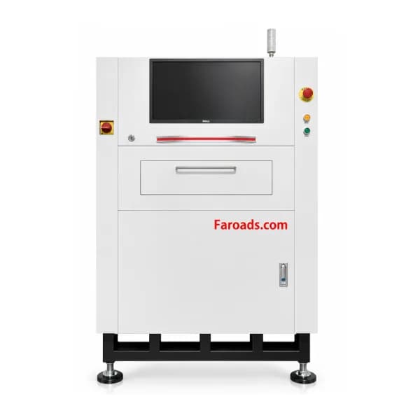
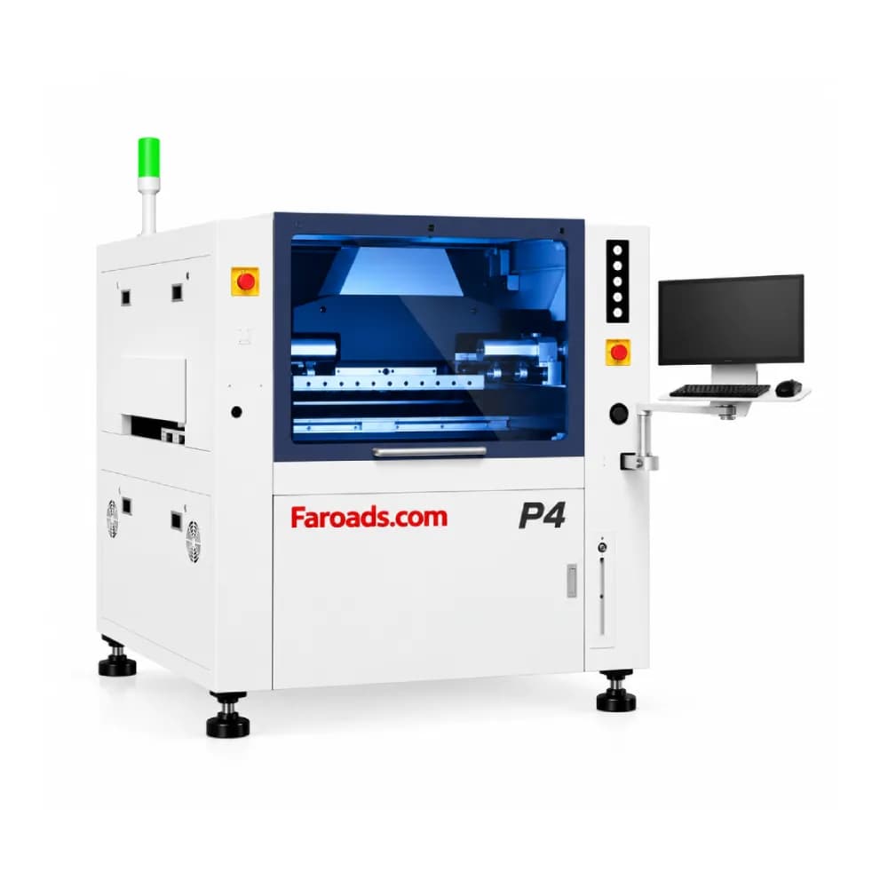
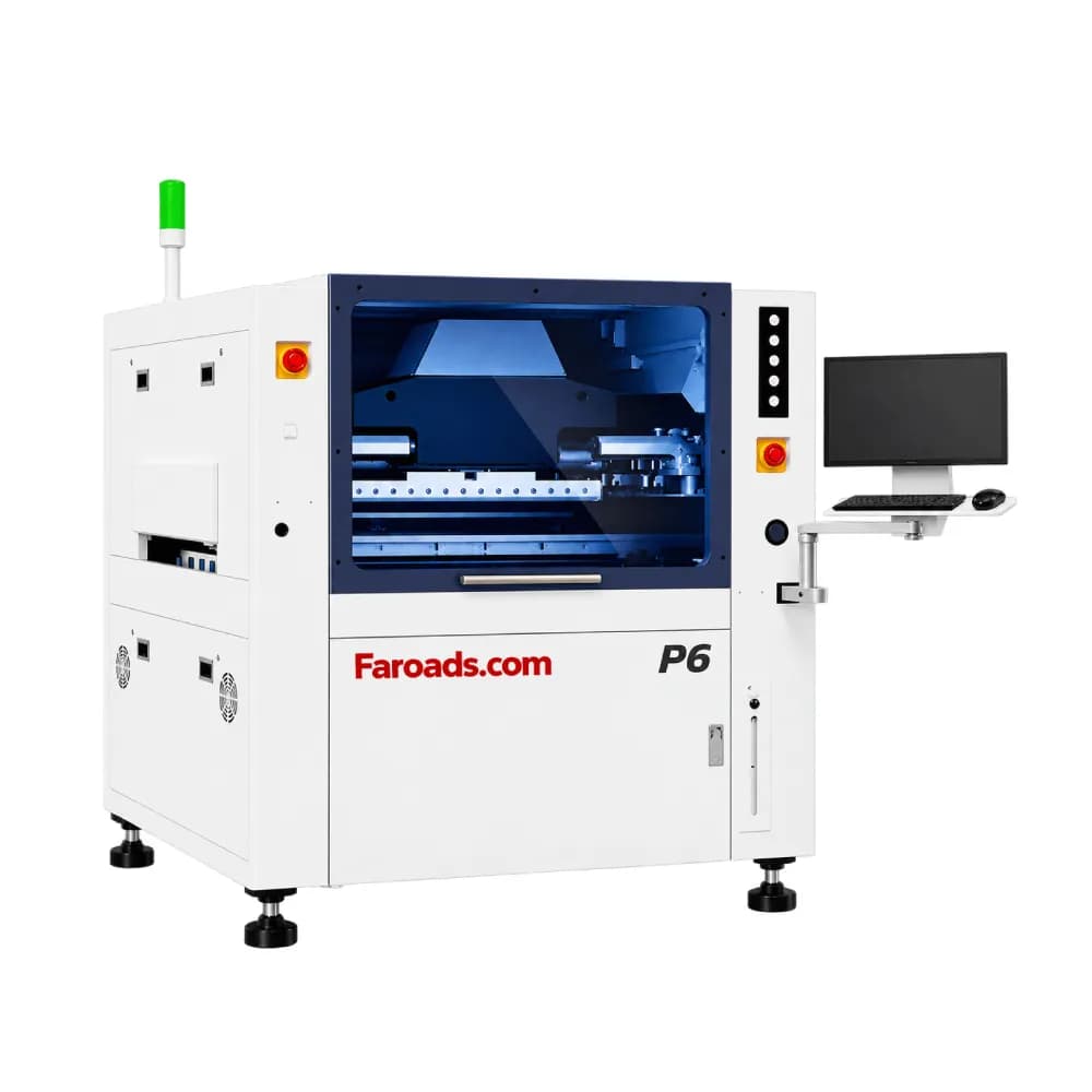
FAROAD's own range shows why this check matters. The P5 printer lists a maximum print size of 510 × 510 mm, and the P6 lists substrates up to 650 × 610 mm. The 3D SPI machine lists a maximum loading and detection size of 450 × 500 mm. Most boards fit both comfortably, but a buyer with very large panels would need to confirm orientation, a different configuration or a different panel design before ordering.
Check thickness, warpage and transfer direction too. The SPI page lists a warped-board measuring range of ±5 mm, left-to-right or right-to-left transfer, and manual or automatic track-width adjustment. Make sure transfer direction and board edge clearance agree with the printer and with the conveyor between them.
Match cycle time to the printer, not the brochure
An SPI that takes longer per board than the printer will slow the line. Compare the two using your own boards.
The P5 page lists a printing cycle time of 7 seconds; the SPI page lists 0.35 to 0.5 seconds per field of view and 0.3 seconds per fiducial mark. The inspection time for a board therefore depends on its area, the resolution chosen and how many fields of view the program needs. As an illustrative example only: a board needing 20 fields of view at 0.4 seconds each, plus two fiducials, would need roughly 8.6 seconds of measurement before handling time. That is longer than the printer's listed cycle, so the program, resolution or panel layout would need review. Ask both suppliers to time the pair with your largest, densest board.
Decide what the feedback loop should actually do

"Closed loop" is used loosely in quotations. Agree in writing what information moves between the machines and what each one does with it.
Typical options range from simple to advanced. At the simple end, the SPI flags a failed board and the operator acts. A step further, the SPI tracks trends such as gradual offset or falling volume, and the line responds with an adjustment or a stencil clean before boards fail. Fully automatic adjustment requires the two machines to share a compatible data interface.
According to FAROAD's SPI page, its measurement results can be passed to the printer and the mounters so the process is adjusted in real time. The P5 page separately describes a closed-loop compensation platform for alignment. Ask which of these work together in your configuration and what has to be set up to enable them. Do not assume that two machines described as "closed loop" will automatically talk to each other.
Printer-integrated 2D check or a separate 3D SPI?
Some printers offer an optional built-in inspection camera. The P5 page, for example, lists an optional 2D inspection system for solder paste after printing. A 2D check can confirm that paste is present and roughly in position, which may be enough for simpler boards.
A separate 3D SPI measures deposit height and volume as well as area and offset. The FAROAD SPI page lists measured items of volume, area, height, XY offset and shape. If your boards carry fine-pitch parts, area-array packages or tight volume requirements, volume measurement is usually the deciding factor. Decide which level of measurement your products need before comparing prices, because the two options answer different questions.
Agree the data before the machines arrive
Inspection produces data, and someone must own it. Decide where SPI results will be stored, who reviews trends and which limits trigger action.
If you run an MES or quality database, specify the connection now. The FAROAD SPI page lists multiple data-format interfaces for MES upload, real-time SPC tools and data integration with pre-reflow and post-reflow AOI. Ask both suppliers for the exact data formats and communication methods, and test them during acceptance.
Run one joint trial
Trial the printer and SPI together with your stencil, paste and boards. Print a run, inspect every board and review the data. Then introduce a deliberate fault, such as a partially blocked aperture, and confirm the SPI finds it and the agreed response follows.
A joint trial also shows whether SPI limits are set sensibly. Limits that are too tight stop good boards; limits that are too loose let poor prints pass.
Frequently asked questions
Do the printer and SPI need to come from the same supplier? No, but one supplier makes interface and data responsibility simpler. If they differ, state in writing who is responsible for the connection.
Can SPI make up for a weak printer? No. SPI finds problems; it does not prevent them. A stable printer with SPI monitoring is the goal.
Where should SPI sit on the line? Directly after the printer, before placement, so a bad print can be cleaned and reprinted without losing components.
What resolution should we choose? It depends on your smallest pads and your cycle-time target. Higher resolution measures more finely but needs more fields of view per board.
Request a printer-and-SPI proposal
Send FAROAD your largest panel, finest-pitch components and target cycle time, and ask for the printer and SPI quoted as one process. Request a quote to receive a matched configuration and a joint trial plan.