SMT Line Board Size: How to Keep Every Machine Compatible
How to specify one board-size window across the SMT line, where FAROAD published envelopes diverge, and why the loader, SPI or dual-track width can be the limiting machine.
6 min read
This article is about making every station on the line accept the same boards: one size window, the machines that are tighter than they first appear, and the dual-track and long-board cases that change the window again. It is not a long-board LED line guide. If the product is a long lighting panel, start with LED SMT lines and long-board fit and then use this article to check the rest of the envelope.
The smallest envelope wins
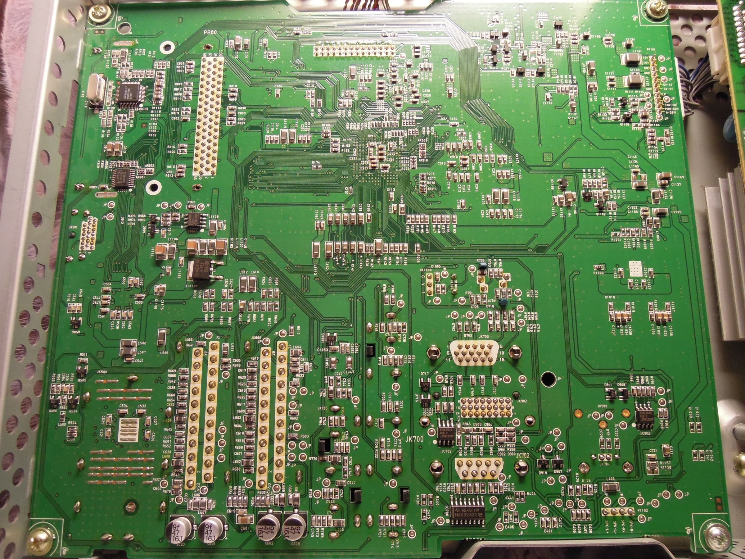
The backside of a large assembled circuit board. Photo: Cmuelle8. Source on Wikimedia Commons, CC0 1.0. Resized from 4000 × 3000 px to 2400 × 1800 px and recompressed as JPEG for publication; not cropped.
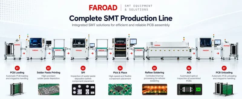
A line is only as useful as its tightest machine. A placement machine that lists a 510 mm-class board size will still idle if the magazine loader stops at 400 × 330 mm, or if the SPI stops at 450 × 500 mm, or if a dual-track configuration narrows the width to 270 mm. The purchase error is usually not a wrong mounter. It is a stack of independently chosen envelopes that were never laid on one sheet.
Write the window before you compare models: minimum and maximum length and width, thickness, weight, edge keep-out, and both orientations if the panel will be flipped. Then apply that window to the loader, printer, SPI, placement machine, oven, AOI and unloader. Any station that cannot hold the full window is either the wrong model, a model that needs a listed option, or a reason to change the panel design.
Where FAROAD published envelopes diverge
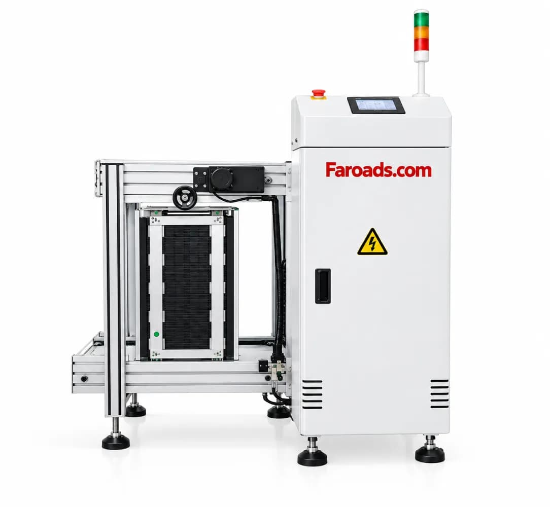
The listed FAROAD figures are specific, and they do not all agree with each other. The L400 magazine loader and UL400 unloader list a PCB size of 50 × 50 mm to 400 × 330 mm, with a magazine size of 460 × 400 × 563 mm. The mini loader lists (50–450) × (50–280) mm. Those handling envelopes are narrower than several of the printers and mounters in the same catalogue, so they are often the first limit on a "standard" line.
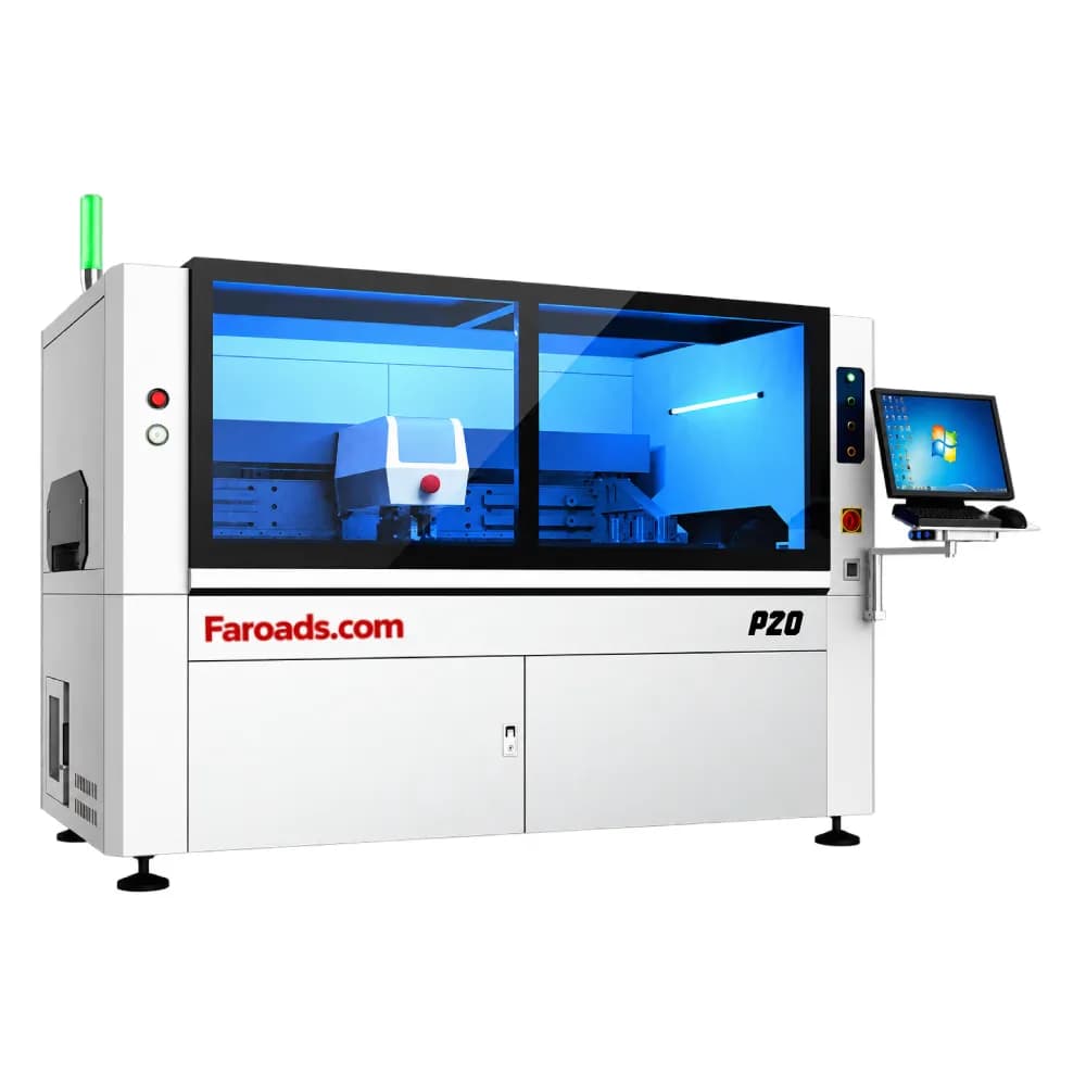
On the printers, the P5 lists a standard print size of 50 × 50 mm to 510 × 510 mm, with PCB thickness of 0.4–6 mm. The P6 lists a minimum substrate of 100 × 80 mm and a maximum of 650 × 610 mm, expandable to 750 × 610 mm, with thickness of 0.6–6 mm. The P20 LED printer lists 50 × 50 mm to 1,500 × 350 mm. A board that fits the P6 can still be too wide for the P5, and a long, narrow lighting panel that fits the P20 will not fit a 510 × 510 mm printer or a 400 × 330 mm loader. Printer-feature comparisons belong in solder paste printer selection; the size window belongs here.
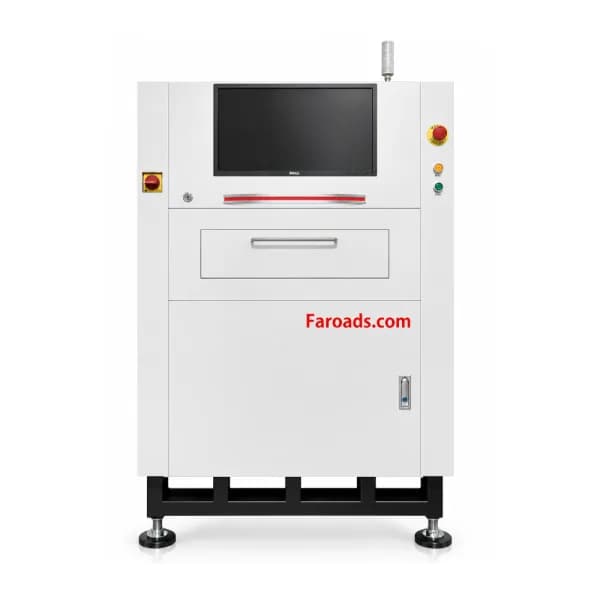
Inspection and placement add further limits. The Inpex 510 SPI lists a largest inspectable board of 450 × 500 mm. The S510 AOI lists 460 × 350 mm; the M400 lists 510 × 460 mm. Both AOI pages list a 3 mm edge width and a thickness of 0.3–5 mm, which is not the same thickness window as the printers. On placement, the CPM-F5 lists a maximum of 510 × 410 mm, the F6 510 × 570 mm, the H6 510 × 510 mm in single track, the S5 510 × 550 mm in single track, and the HX40 only 320 × 580 mm. Those placement windows are the right input to pick-and-place selection, but they must still clear the stations on either side.
On single-track MS tables, and on the MK-8 table, rail width is published as 50–490 mm. Dual-track MS models publish 50–275 mm per track. A 700 mm width appears on the MK-8MAX lighting-oven page. Do not copy that MAX-series figure onto the MK-10MAX or MK-12MAX; those pages do not clearly list it. Confirm oven width on the exact model in the order.
Dual-track and long-board special cases
Dual-track placement tightens the window. The H6 dual-track maximum is 510 × 270 mm; the S5 dual-track maximum is 510 × 300 mm. Each page also mentions a 1,200 mm modification, which is not the standard column. If you need that length, name the altered envelope on the order and demonstrate the panel in that configuration. A board that fits single-track will not necessarily run two-up inside the standard dual-track widths.
Long boards have the same problem in the other axis. A P20 that prints 1,500 × 350 mm is useful only if the mounter, oven, inspection and handling can accept that length and that width. Lighting-specific placement and oven choices are covered in the long-board and LED oven articles. For every other product, treat a long panel as a line-wide constraint, not as a printer-only option.
Thickness, weight and the rail edge
Length and width are not the whole envelope. The P5 lists PCB weight of ≤4 kg in one table row and a substrate weight of ≤5 kg in another; confirm the applicable figure in the quotation. The P20 lists ≤4 kg. The S510 AOI lists a 5 kg maximum; the M400 lists 7 kg. Placement machines list thickness ranges of 0.5–9.0 mm on the F5, F6, H6 and S5, and 0.4–9.5 mm on the HX40, which is not the same as the printer or AOI thickness windows.
Edge keep-out matters on AOI, and rail contact matters on the oven and the mounter. A panel that is dimensionally inside the maximum, but has copper or components in the clamped edge, will still fail at transfer. Include the edge condition in the window, and include both orientations if the board is flipped.
Confirm the window on the real panels
Ask for a handling and process trial that uses your largest panel, your smallest panel, and your thickest or heaviest assembly. The trial should pass the loader or other infeed, the printer, any SPI, the placement machine in the intended track configuration, the oven and the AOI, then the unloader. If the line uses magazines, use the magazines you will run, not a loose hand-feed. The PCB loader and unloader buying checklist covers magazine compatibility in more detail.
A drawing that "almost fits" is not a specification. If a model only meets the window with an option or a modification, that option should be on the order.
Frequently asked questions
Why would a 510 mm-class mounter still reject my board? Because another station may be tighter. The listed L400 and UL400 stop at 400 × 330 mm, the SPI at 450 × 500 mm, and the S510 AOI at 460 × 350 mm. The HX40 tops out at 320 × 580 mm. The tightest station sets the line.
Can I use the P20's 1,500 mm length as the line length? Only if every other station is specified for that length and for the 350 mm listed width. The P20 figure is a printer envelope, not a line envelope.
Does dual-track on the H6 or S5 accept the same boards as single track? Not at the standard listed widths. Dual-track maxima are 270 mm on the H6 and 300 mm on the S5. Any 1,200 mm alteration has to be written into the quotation and shown on a trial.
Should I assume the MK-10MAX accepts 700 mm-wide boards because the MK-8MAX lists that width? No. The 700 mm figure is listed on the MK-8MAX page. Confirm belt or rail width on the specific MAX model you are buying.
Request a line-wide size review
Send FAROAD the minimum and maximum panel size, thickness, weight and edge condition, including both orientations if you run two-sided boards. We will compare that window with the listed envelopes for each station and identify the limiting machine before you order. Request a quote to start that review.