PCB Panelization for SMT Assembly: Panel Choices That Affect Your Equipment
How panel size, rails, fiducials, bad-board marks and separation method change printer, mounter, inspection and handling performance, and which panel rules to agree before you buy an SMT line.
4 min read
A panel is decided by the PCB designer and the board fabricator, often long before anyone thinks about the SMT line. Yet the panel determines how many boards each printer stroke covers, how long the mounter spends on fiducials, how heavy a magazine gets and how the boards are separated afterwards. If you are buying or upgrading a line, agree the panel rules with design and fabrication at the same time. This guide covers the decisions that touch the equipment. The size limits of each station are covered in our board size compatibility guide.
Why panel size changes throughput
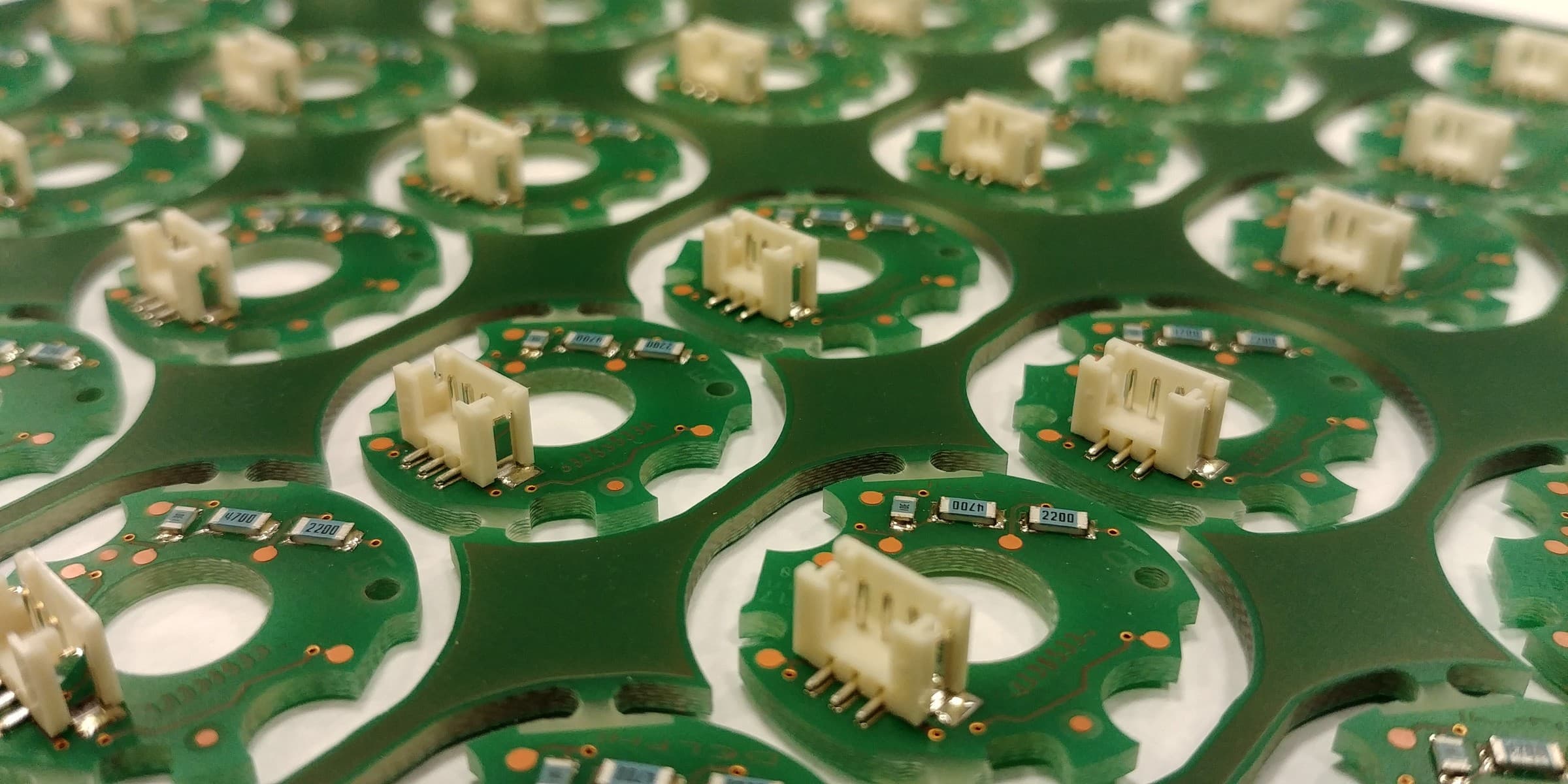
Identical printed circuit boards still joined in one production sheet. Photo: Gabriela P. Source on Wikimedia Commons, CC BY 4.0. Resized from 4160 × 2080 px to 2400 × 1200 px and recompressed as JPEG for publication; not cropped.
Each station has fixed work per panel: transfer in and out, clamping, fiducial recognition, a print stroke, a cleaning cycle and an inspection setup. More boards per panel spread that fixed time across more units.
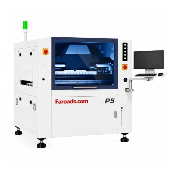
As an illustrative calculation, the FAROAD P5 lists a 7-second core print cycle. With one board per panel, printing alone accounts for 7 seconds per board before transfer time. With six boards per panel, the same cycle works out to just over one second per board. The same logic applies to transfer and fiducial time on the mounter and to setup time on the AOI. Larger panels are not always better, though: they add weight, may not fit the narrowest station, and lose more boards when one area is scrapped.
Rails and edge clearance
Machines hold panels by their edges. Mounters on the FAROAD CPM range list pneumatic or electric lifting platforms with upper and lower clamps, and the S510 and M400 AOI list a 3 mm edge width. Components or pads too close to the clamped edge get covered, shadowed or damaged.
Break-off rails along the conveyor edges keep that zone clear and give room for tooling holes and fiducials. Agree a rail width that satisfies the strictest station on the line, and confirm it with each supplier rather than copying a rule from another factory.
Fiducials and bad-board marks
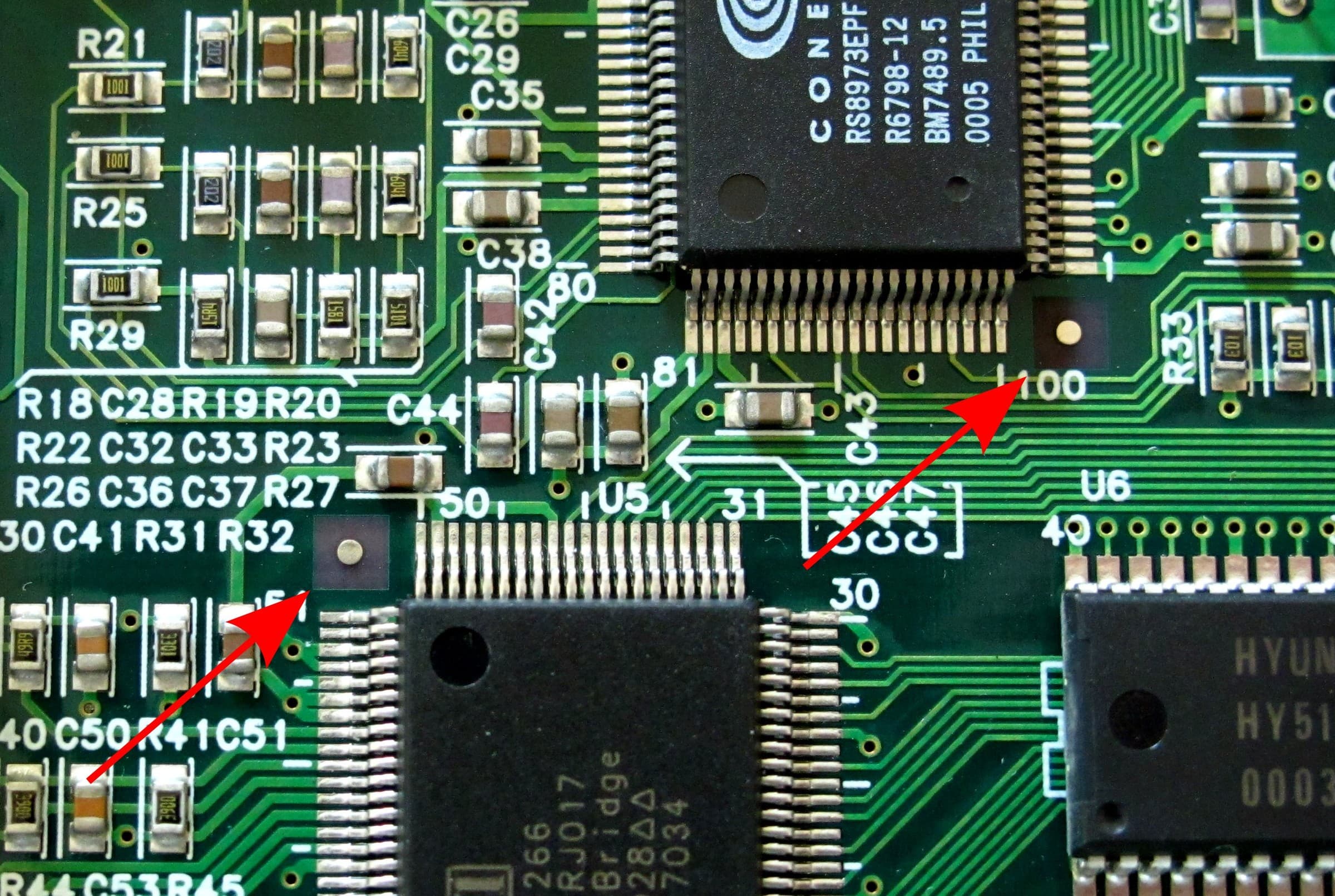
Fiducial marks on an assembled board, indicated by red arrows. Photo: wdwd. Source on Wikimedia Commons, CC BY-SA 3.0. Resized from 2512 × 1688 px to 2400 × 1612 px and recompressed as JPEG for publication; not cropped. This file is shared under the same license.
Fiducials let the printer, SPI, mounter and AOI find the panel. Place global fiducials on the rails, well apart, and add local fiducials near fine-pitch parts on each board. The CPM-F5, F6, H6 and S5 list a 20 × 20 mm mark camera field of view and the HX40 lists 10 × 10 mm, so keep each fiducial and its clear area well inside that window.
Bad-board marks tell machines to skip a board that failed fabrication or an earlier process. The Inpex 510 SPI lists automatic bad-board mark recognition and 0.3 s per mark point. The CPM pages do not explicitly list bad-mark skipping, so confirm whether and how the quoted mounter supports it before relying on it.
Panel size against every station
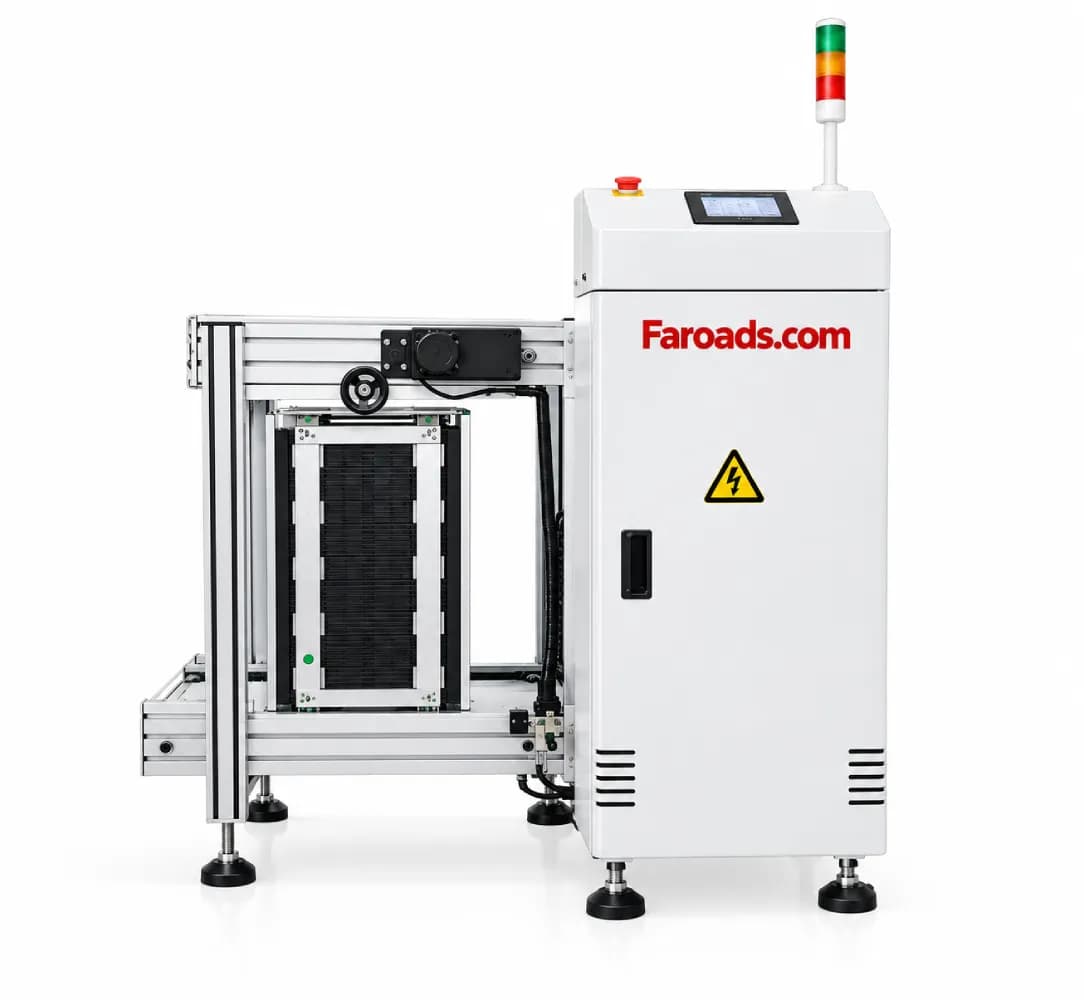
The panel must sit inside every machine's window, not just the mounter's. On the FAROAD listings, most stations accept a 50 × 50 mm minimum, but the P6 printer starts at 100 × 80 mm. At the large end, the L400 loader stops at 400 × 330 mm, the Inpex 510 SPI at 450 × 500 mm, the S510 AOI at 460 × 350 mm and the HX40 at 320 × 580 mm. Running a mounter in dual-track mode also narrows the usable width, so check that figure on the H6 or S5 if you plan two lanes. Panel weight must also stay inside printer, AOI and handling limits. Our loader and unloader checklist covers magazine fit.
Plan the separation step
Panels are usually separated by V-score lines or by routed tabs with small perforations. V-scores are quick but need straight edges and keep parts away from the score line. Routed tabs allow irregular outlines but leave tab remnants and need a router or punch. Both stress nearby components, especially ceramic capacitors close to the break line.
FAROAD lists PCB depaneling as coming soon, so plan the separation equipment or service separately and include it in the line budget and layout.
Agree the panel before the line trial
Before the trial, write a short panel specification covering:
- Panel outline, board count and orientation.
- Rail width, tooling holes and edge keep-out.
- Global and local fiducial positions and sizes.
- Bad-board mark position and whether each station uses it.
- Panel weight, finished thickness and maximum warp.
- Separation method and component keep-out from the break line.
Then run the trial on production panels. Output measured on single boards or a different panel will not predict the real line. The capacity planning guide shows how to turn panel results into line output.
Finally, keep a copy of the agreed panel specification with the line documents, so future products are designed to the same rules and do not reopen the question.
Frequently asked questions
How many boards should go on a panel? Enough to spread fixed station time, but not so many that the panel exceeds the narrowest machine window, gets too heavy or wastes good boards when one fails. Who should own the panel design? Design, fabrication and assembly together. The assembler's equipment limits should be written into the panel rules before the fabricator quotes. Do I need fiducials on every board in the panel? Global fiducials on the rails are standard. Local fiducials near fine-pitch parts help each board on the panel be corrected individually. Does FAROAD supply depaneling equipment? PCB depaneling is listed as coming soon on the FAROAD equipment page. Plan separation as a separate item for now.
Check your panel against a FAROAD line
Send FAROAD your panel drawing with board count, rails, fiducials and weight. We will compare it with each station and suggest changes before you commit. Request a quote to start.