Flex PCB Assembly: What Your SMT Printer, Mounter and Oven Need
How flexible and rigid-flex circuits change the SMT line: carriers, printer support, fiducials and warp detection, SPI compensation and reflow, checked against FAROAD's listed specifications.
4 min read
Flexible circuits and rigid-flex boards appear in cameras, wearables, displays, medical devices and vehicle electronics. They are assembled with the same SMT process as rigid boards, but they do not behave like rigid boards on rails, under a stencil or in an oven. This guide explains what changes at each station and what to settle with your equipment supplier before you order. It assumes the flex design is already fixed; it is not a flex layout guide.
Flex circuits travel on carriers
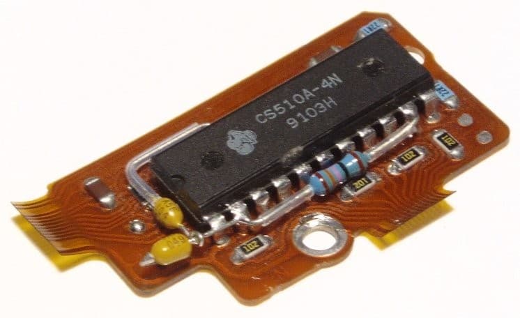
A flexible printed circuit with surface-mount and through-hole components, bonded to a rigid support. Photo: Richard Wheeler (Zephyris). Source on Wikimedia Commons, CC BY-SA 3.0. Recompressed as JPEG for publication; not cropped or resized. This file is shared under the same license.
A bare polyimide circuit is far thinner than the minimum board thickness most SMT machines list. On the FAROAD listings, the P5 and P20 printers start at 0.4 mm and the P6 at 0.6 mm; the CPM-F5, F6, H6 and S5 mounters list 0.5–9.0 mm; the HX40 and the L3 LED machines list 0.4–9.5 mm; the S510 and M400 AOI list 0.3–5 mm. A thin flex circuit is below most of those minimums, and it cannot be clamped by its edges without buckling.
The usual answer is a rigid carrier, sometimes called a pallet or fixture, that holds the flex flat through printing, placement, reflow and inspection. Carriers use magnets, vacuum, high-temperature tape or clamps. They are product tooling, designed around each circuit, and FAROAD does not list carriers as a product. Plan who designs and supplies them, how many you need in circulation, and how they return to the start of the line; FAROAD does not list a return conveyor.
Rigid-flex panels with rigid outer rails can sometimes run without a carrier, if the rails meet each station's thickness and edge requirements. Confirm that with a handling trial.
Printing on a carrier
The printer must seal the stencil against a surface that is flat to within a small fraction of a millimetre. The carrier, not the flex, sets that flatness, so it should be specified as precisely as the stencil.
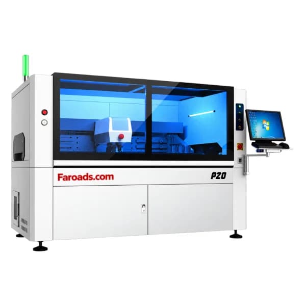
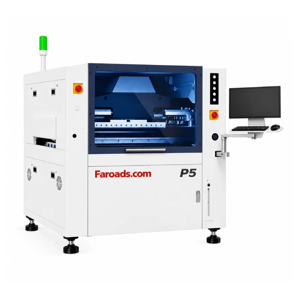
The FAROAD P4, P5 and P6 pages list pins and blocks under the board, a vacuum cavity that can be spliced to suit the carrier, side clamps that can be withdrawn, and platform height that calibrates itself to board thickness. Those help hold a carrier steady. Use the combined carrier-plus-flex thickness when checking the printer's thickness range and weight limit. Separation speed is listed as adjustable from 0.1 to 20 mm/s on the P5 and P6, which matters when paste release from a lightly held substrate is marginal.
Placement and inspection on a moving substrate
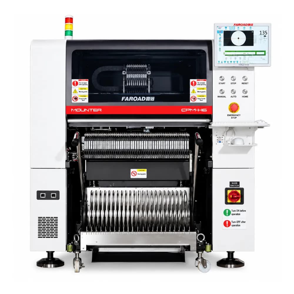
Flex circuits stretch and shift slightly in their carriers, so each circuit should carry its own local fiducials. Global panel fiducials alone may not correct the offset of every circuit on the carrier.
For warp, the CPM-H6 and HX40 list laser substrate warping detection as an option, and the CPM-F6 lists substrate warping detection. Ask how the option measures height on a carrier and whether it can slow or skip a placement. Our warpage equipment guide explains the wider topic.
Paste inspection is where FAROAD lists a flex-specific feature. The Inpex 510 3D SPI describes FPC warpage compensation that combines Z-axis dynamic compensation with telecentric-lens static compensation, and lists a maximum measuring height for warped boards of ±5 mm. If flex printing is new to your plant, SPI is the station that shows whether the carrier is doing its job. Our 3D SPI selection guide covers the rest of the specification.
Reflow: carrier mass and moisture
The carrier goes through the oven with the circuit, and it often has more thermal mass than the flex. Profile the assembly on its carrier, with thermocouples on the flex near the largest component, not on a bare test board.
Polyimide absorbs moisture. Many flex suppliers recommend baking circuits before reflow and limiting the time between baking and soldering; follow your laminate and flex supplier's guidance. On FAROAD rail ovens, the carrier rides on the rails, and the MS pages list 30 mm upper and 20 mm lower clearance (the MK-8 lists 30 mm and 25 mm). Check that the carrier and its tallest part fit. Our rail vs mesh belt guide explains when a different conveyor makes sense.
Questions to settle before quoting
- Who designs, supplies and maintains the carriers, and what are their outer dimensions, thickness and weight?
- Do those dimensions sit inside every station's board window? See our board size compatibility guide.
- How many carriers are needed to keep the line full, and how will they be returned and cleaned?
- Which stations need local fiducial recognition, warp detection or SPI compensation?
- What bake and storage rules apply to the flex material?
Then run the trial on carriers built to production drawings, not on a hand-taped sample.
Budget time for carrier iteration. First-article carriers often need adjustments to hold-down points, cut-outs for underside parts or vent holes, and each change needs another print and reflow check.
Frequently asked questions
Can a standard SMT line assemble flex circuits? Usually yes, with carriers designed for each product and a profile set for the carrier. The machines must accept the carrier's size, thickness and weight. Does FAROAD supply flex carriers? Carriers are not listed as a FAROAD product. They are normally designed per product by a fixture supplier or in-house, and should be ready before the line trial. Is SPI more important on flex? It is very useful, because uneven support shows up first in paste height and volume. The Inpex 510 lists FPC warpage compensation for that reason. Should flex circuits be baked before reflow? Many flex suppliers recommend it because polyimide absorbs moisture. Follow the bake time, temperature and floor-life limits from your material supplier.
Plan your flex assembly line
Send FAROAD your flex drawings, carrier concept and target output. We will check carrier dimensions against each station and propose a trial plan. Request a quote to begin.