Pin-in-Paste Reflow: Can Your SMT Line Solder Through-Hole Parts?
When pin-in-paste (intrusive reflow) lets an SMT line solder selected through-hole connectors, what it asks of the printer, mounter, oven and inspection, and when wave or selective soldering is still the better route.
5 min read

Many boards are almost all surface mount, with a handful of through-hole connectors, headers or power parts. Those few parts can force a second soldering process: wave, selective or hand soldering. Pin-in-paste, also called intrusive reflow or through-hole reflow, solders suitable through-hole parts in the same reflow pass as the SMT components. This guide explains when it works and what it asks of the equipment you are buying. FAROAD lists wave and selective soldering as coming soon, so this article focuses on what an SMT line can do on its own.
How pin-in-paste works
Paste is printed onto and into the plated through-holes, the through-hole part is inserted so its pins push through the paste, and the board goes through reflow with everything else. The paste melts, wets the barrel and the pins, and forms fillets on both sides.
The catch is volume. Solder paste is roughly half flux by volume, so the wet deposit must be about twice the solder the joint needs: the space between pin and barrel plus top and bottom fillets. A normal stencil aperture rarely holds that much. Process engineers add volume with overprinting beyond the pad, stepped stencils that are thicker in one area, or solder preforms.
Which through-hole parts qualify
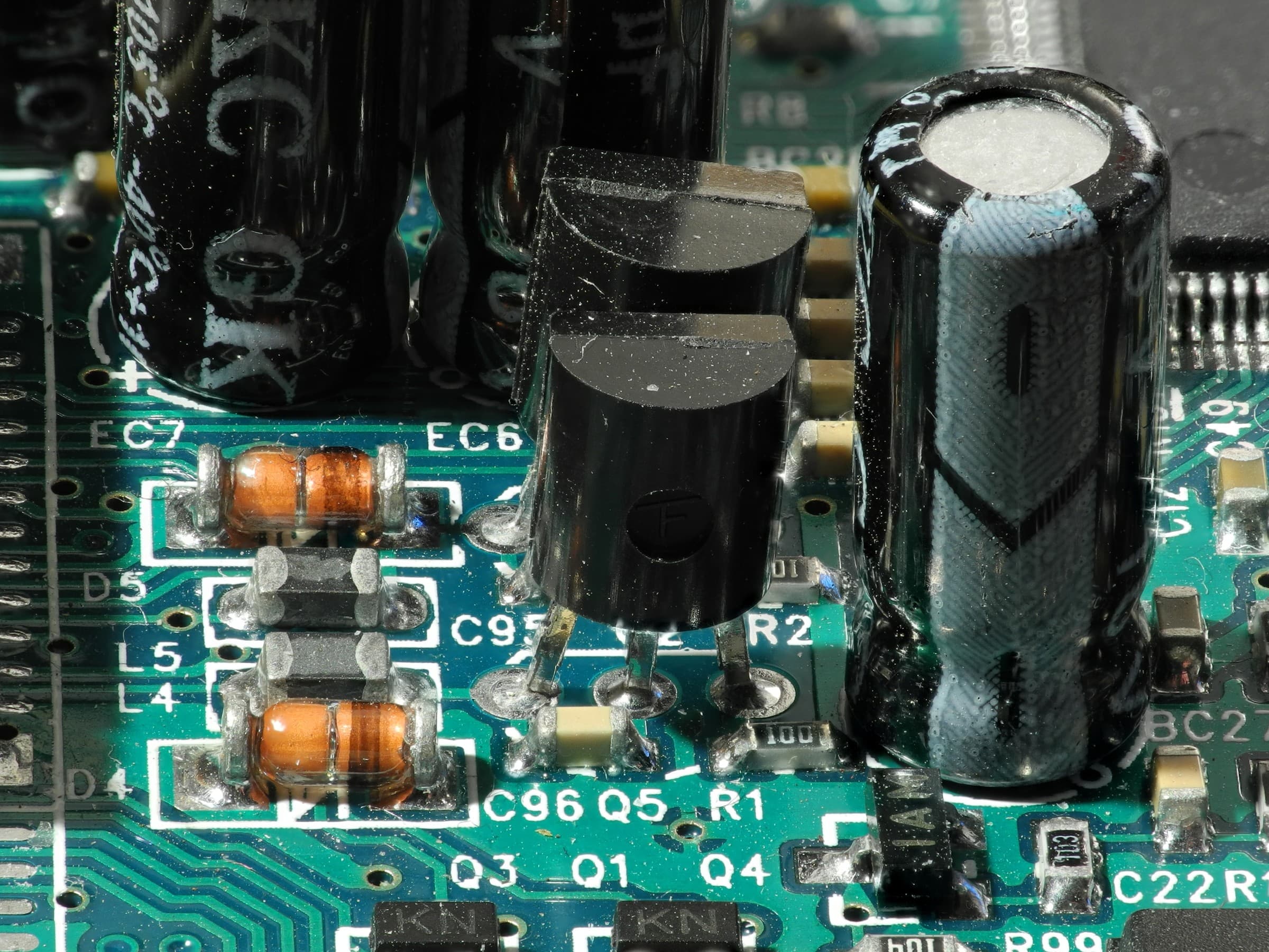
A mixed-technology board with surface-mount chips alongside through-hole electrolytic capacitors and inductors. Photo: Thomas Bresson. Source on Wikimedia Commons, CC BY 3.0. Resized from 3648 × 2736 px to 2400 × 1800 px and recompressed as JPEG for publication; not cropped.
The component, not the paste, is usually the limit. A part qualifies when:
- Its body is rated for your reflow peak. In wave soldering the body stays above the heat; in reflow it sees the full profile. Many connector families offer reflow-rated versions.
- It has standoff so flux can escape and the top fillet can form.
- Its pin length suits the board thickness. Long pins push paste out of the barrel.
- Its thermal mass is moderate. Very heavy parts, or pins tied into large copper planes, may not reach wetting temperature in a profile set for the rest of the board.
Parts that fail these tests, such as some relays, electrolytic capacitors or unrated plastic housings, stay with selective, wave or hand soldering.
What the printer and SPI must handle
Overprints and step stencils need a printer that holds the stencil firmly and controls pressure and separation. The FAROAD P4, P5 and P6 pages list software-controlled squeegee pressure, adjustable demoulding speed, automatic stencil positioning and wet, dry and vacuum cleaning; the P6 lists a print gap up to 20 mm and print pressure up to 20 kg. Confirm the stencil frame range covers a stepped stencil.
Large deposits also test SPI. The Inpex 510 lists a maximum measuring height of ±550 μm, with ±1,200 μm optional. If your overprints or steps approach that height, ask for the option and verify measurement on your deposits. Our printer and SPI pairing guide covers how those two machines should be specified together.
Inserting the through-hole parts
There are two ways to get pins into the paste: the mounter or a person.
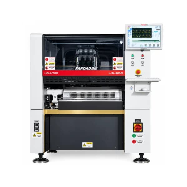
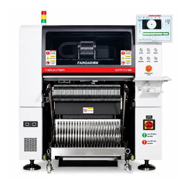
A placement machine can insert some through-hole parts if the part fits its recognition and feeding range. The CPM-F6 lists a fixed-camera range up to 55 × 55 × 25 mm, tube feeders and an optional tray cabinet, and an optional force control management function. Ask whether the head and nozzle can press the specific part into the holes reliably, and how pin alignment is checked. FAROAD's odd-form and through-hole insertion equipment is listed as coming soon, so do not assume dedicated insertion heads.
Manual insertion between placement and reflow works for low volumes but adds labour, a station and a risk of disturbing placed parts.
Reflow and inspection
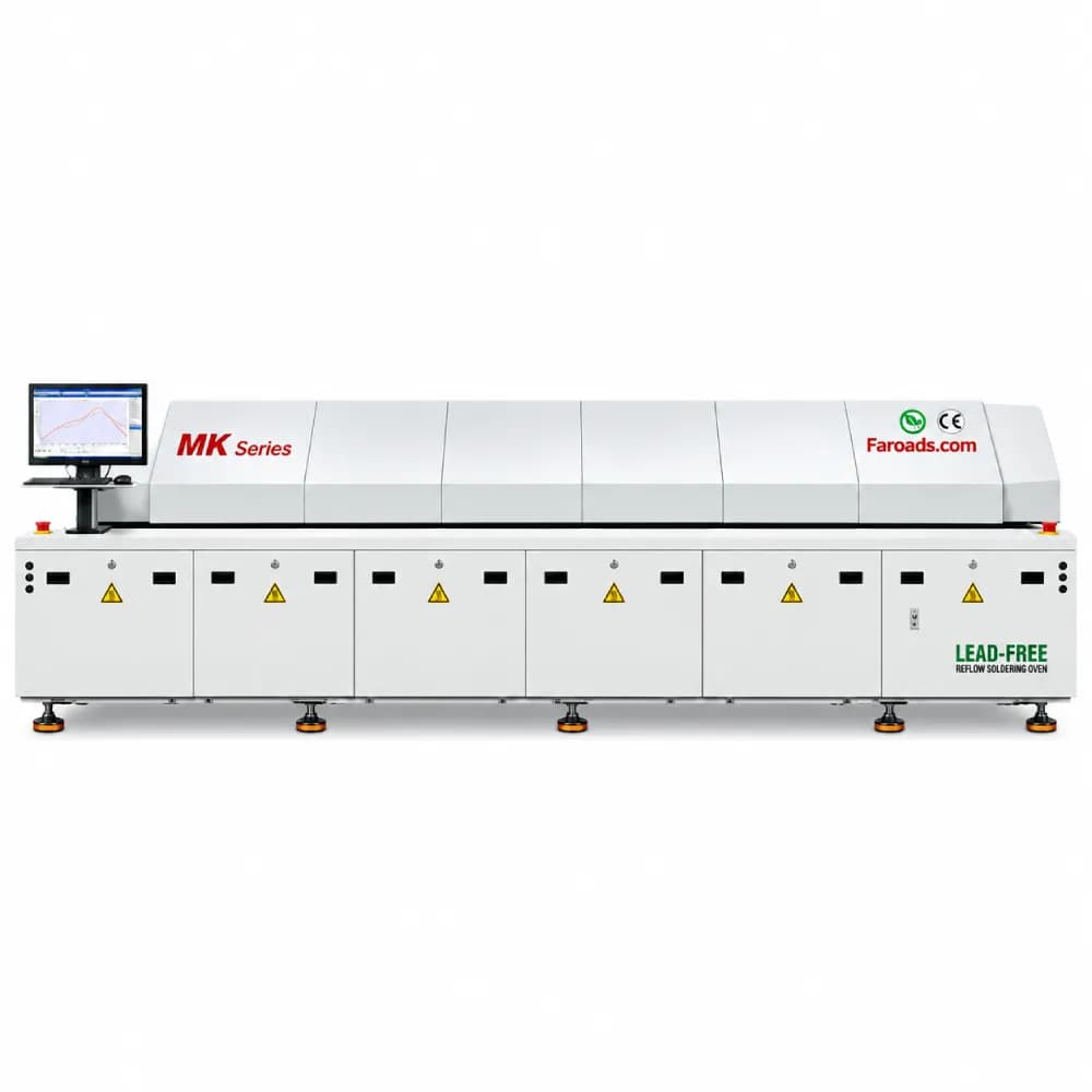
Tall through-hole parts must fit the oven. FAROAD MS rail ovens list 30 mm upper clearance and MK rail ovens 30 mm upper and 25 mm lower; the MK-8MAX LED oven lists 60 mm upper clearance. Profile with a thermocouple at a through-hole joint, not only at SMT pads, because the barrel is often the last area to reach temperature. Our power electronics line guide covers similar heavy-part issues.
Top fillets can be checked by 2D AOI if the part does not shade them; the S510 lists 30 mm top clearance as standard and up to 50 mm adjustable. Barrel fill is hidden. Industry acceptance criteria such as IPC-A-610 commonly call for at least 75 % vertical fill on plated through-holes for many classes. That needs X-ray or cross-sections during qualification. FAROAD X-ray is listed as coming soon.
When wave or selective soldering is still better
Pin-in-paste is strongest when a board has a few reflow-rated parts and everything else is SMT. It is weaker when there are many through-hole parts, heavy transformers or unrated components, or when the stencil cannot hold enough paste without bridging. In those cases a separate soldering process is still the honest answer; FAROAD currently lists wave and selective soldering as coming soon.
Before committing, build a short list of every through-hole part on the board with its reflow rating, pin length, hole size and required fillet. That list decides how many parts can move to pin-in-paste and how many stay with another process.
Frequently asked questions
Can pin-in-paste remove the wave step completely? On some boards, yes, if every through-hole part is reflow-rated and the stencil can deliver enough paste. Many boards keep one or two parts for selective or hand soldering. Does pin-in-paste need a special oven? No special oven type, but the oven must fit the tallest part and the profile must bring through-hole joints to temperature without overheating small parts. Can the pick-and-place machine insert connectors? Some, if they are inside the fixed-camera and feeder range and the head can apply the right force. Test the actual connector before relying on it. How do we check barrel fill? With X-ray or cross-sections during qualification, then with sampling plans in production.
Review your through-hole parts with FAROAD
Send your BOM and board drawing with the through-hole parts marked. We will check which could suit pin-in-paste on a FAROAD line and what printer, mounter and oven settings to trial. See the CPM-F6 specifications or request a quote.